Lab 4: Motors and Open Loop Control
ECE 4160 – Fast Robots
Objective
The purpose of this lab was to set up open loop control of the car, eliminating the need to manually control it. This involved soldering all of the necessary components to the artemis board, writing code to control the motors, and then testing it.
PreLab
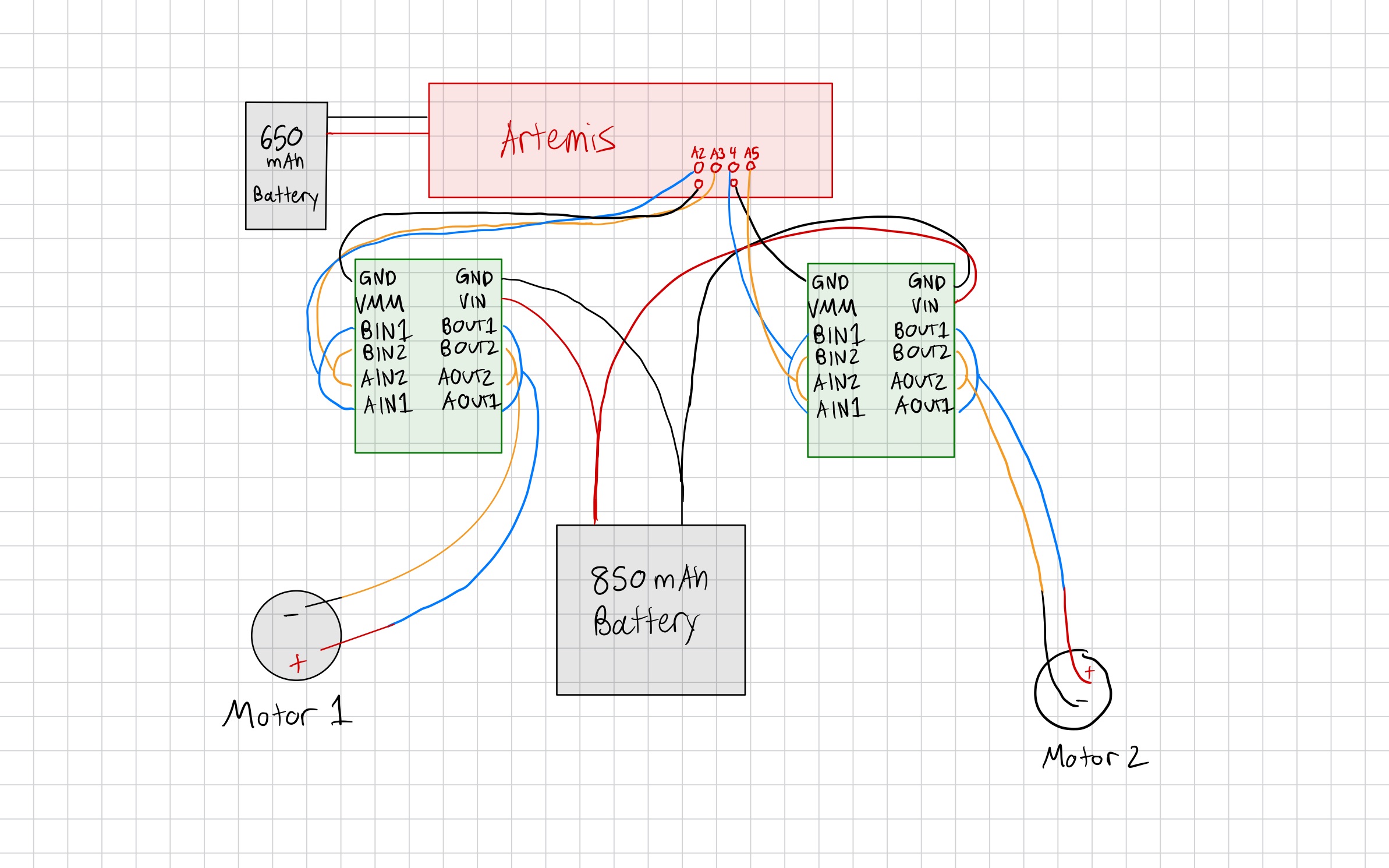
I chose pins A2 and A3 for my first motor driver and pins 4 and A5 for my second. I chose ports that wouldn't require long wires to reach the motor drivers that are mounted on the opposite side of the car from the artemis board.
We power the Artemis separately from the motors because DC motors draw large, noisy current spikes that cause voltage sag and electrical noise on the supply rail. Sharing a battery can lead to resets and corrupted sensor/BLE behavior, so separate power keeps the Artemis supply clean and stable.
When approaching this lab I had to think ahead to how I was going to set everything up in the car. This was important because I didn't want my wires to be too long or not long enough. I wanted to give some wiggle room but didn't want an excess length of cables inside my car. Longer cabels would also increase the risk of noise and interference, which could cause issues with the motors and sensors.
Tasks
Testing the Motor Drivers
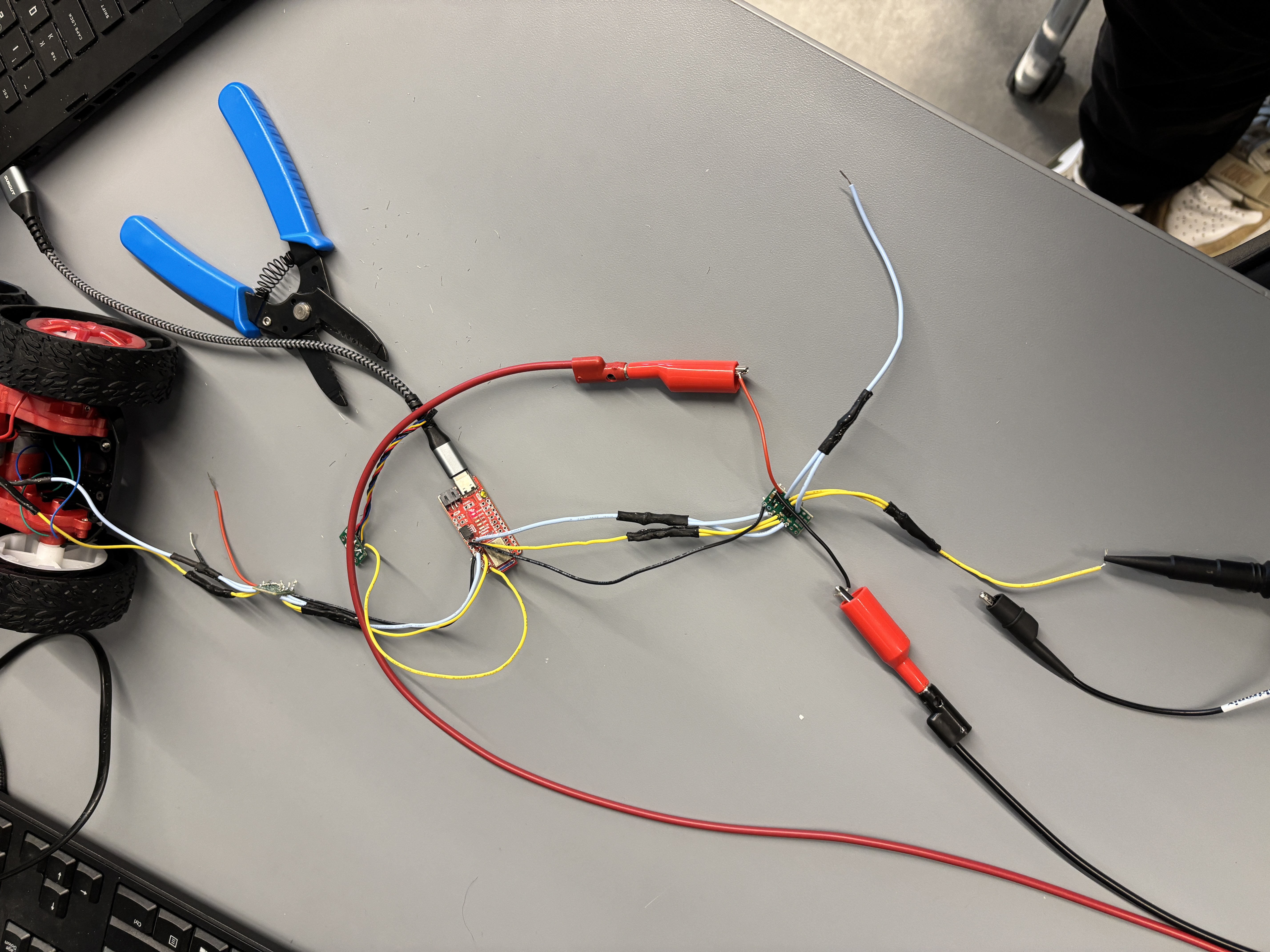
I first sodered wires to both motor drivers as seen in my diagram. I then hooked up the motor driver to an external power supply set to 3.7 V. This seemed quite reasonable since the motor drivers would eventually be powered with a 3.7 V battery.
Next I wrote the following code to loop through PWM values and assign them using analogWrite commands. This allowed me to regulate the power of the motor drivers.
            #define motorL1 A2
            #define motorL2 A3

            void setup() {
            pinMode(motorL1, OUTPUT);
            pinMode(motorL2, OUTPUT);
            }

            void loop() {
            analogWrite(motorL1, 0);
            for (int i = 0; i < 256; i++) {
                analogWrite(motorL2, i);
                delay(10);
            }
            }
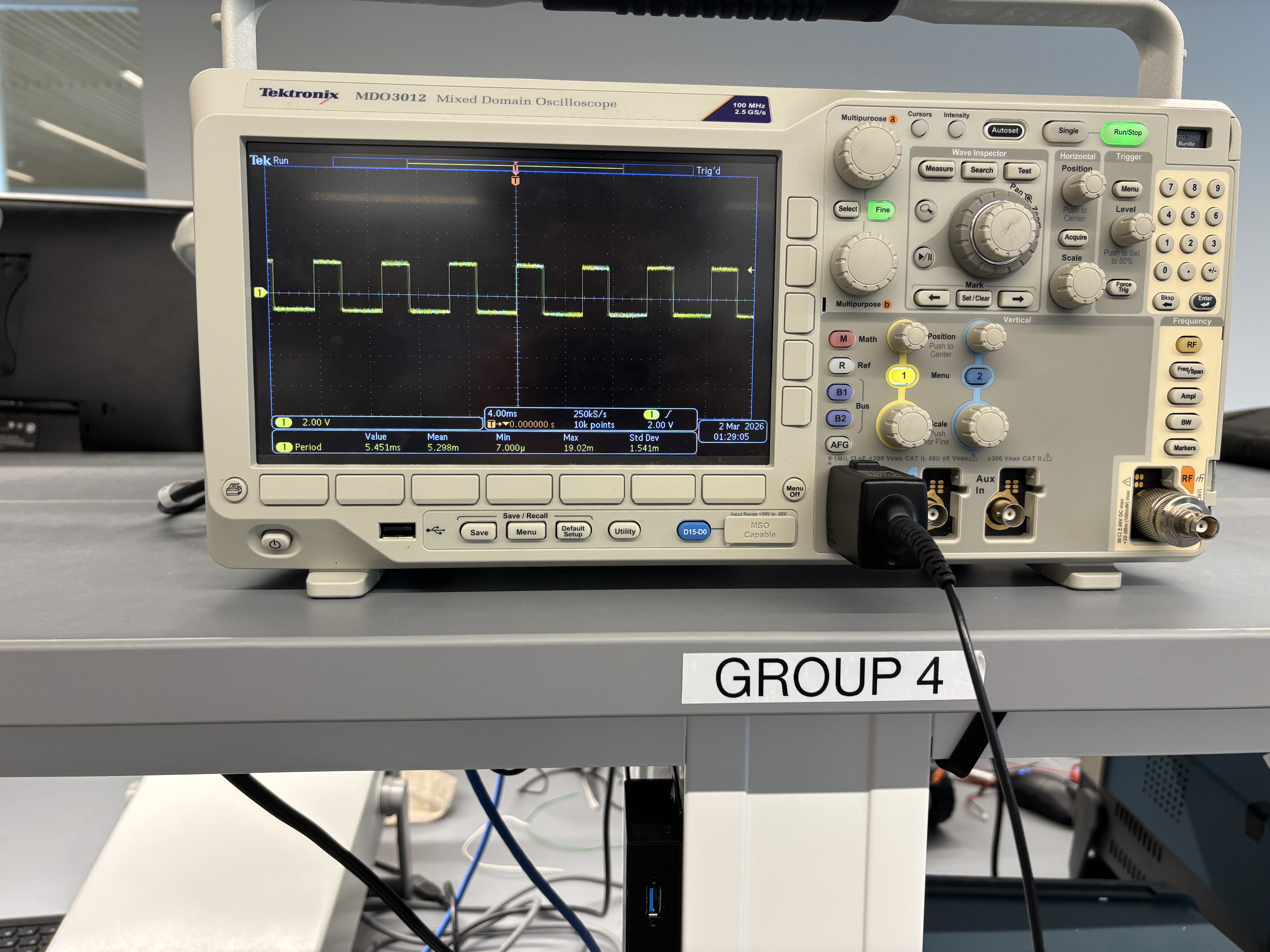
Here are the results from using the oscilloscope to measure the PWM signal:
Taking the Car Apart
Next I took the car apart and removed the leds and their respective wires. I also removed the control PCB and cut all connecting wires to the motors. I then soldered the wires from my motors drives to the actual motors and tested spining the wheels on both sides of the car to ensure everything was working properly. Below is a video of this working.
Power
I then connected the motor drivers to the 850mAh battery so that I would no longer need to use the external power supply. After this I ensured that the same code worked to spin the wheels as when I had used the external power supply.
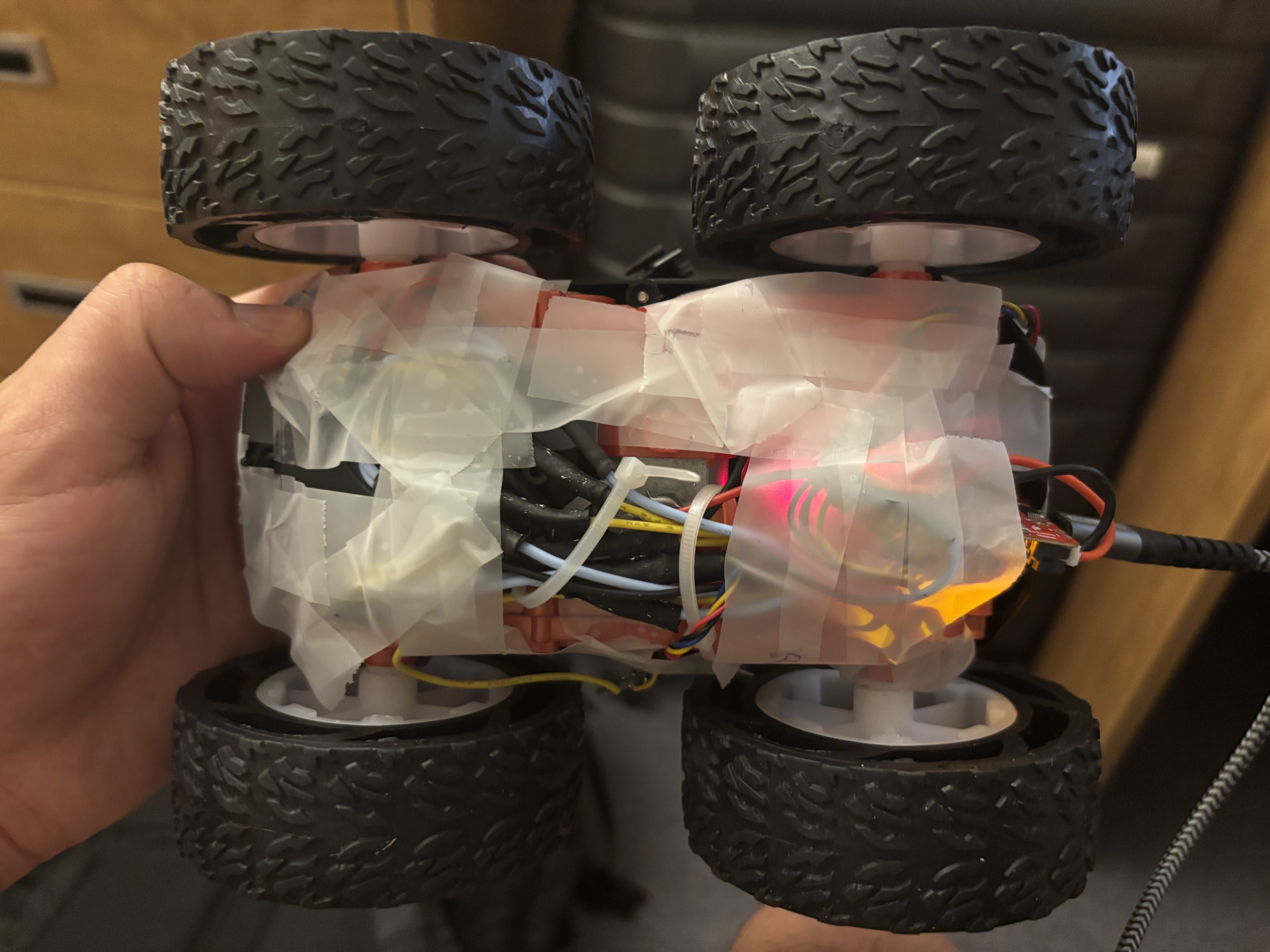
Installation
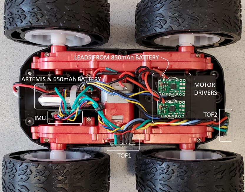
After ensuring that the motor drives worked properly, I installed everything into the chassis. I set up all the components in the same locations as what was shown for the lab instructions (since it is hard to see under the tape) except I moved the two TOF sensors to the opposite sides. I then used zip ties to group wires together and keep everything organized. I then used scotch tape to secure everything down, however I plan to switch to duct tape when I can get access to some as I believe it would make the setup more secure.
Lab diagram for reference:
Both wheels spinning using battery
Running the Car
Finally, I was able to run the code on the ground. First I found the minimum PWM value that allowed the car to actually move forward. This came out to be a PWM of 75 for the left motor and 50 for the right motor (on my carpet floor)
            #define motorL1 A2
            #define motorL2 A3
            #define motorR1 4
            #define motorR2 A5


            void setup() {
            pinMode(motorL1, OUTPUT);
            pinMode(motorL2, OUTPUT);
            pinMode(motorR1, OUTPUT);
            pinMode(motorR2, OUTPUT);
            }

            void loop() {
            analogWrite(motorL1, 0);
            analogWrite(motorR1, 0);
            delay(10000);

            analogWrite(motorL2, 70);
            analogWrite(motorR2, 45);
            delay(1500);
            analogWrite(motorL2, 0);
            analogWrite(motorR2, 0);
            delay(10000);
            }
I then switched to higher speeds yet the motors were not balanced. I then did some calibration since the motors were not perfectly balanced. After calibration, I was able to ensure that the car moved in a relatively straight line.
            #define motorL1 A2
            #define motorL2 A3
            #define motorR1 4
            #define motorR2 A5


            void setup() {
            pinMode(motorL1, OUTPUT);
            pinMode(motorL2, OUTPUT);
            pinMode(motorR1, OUTPUT);
            pinMode(motorR2, OUTPUT);
            }

            void loop() {
            analogWrite(motorL1, 0);
            analogWrite(motorR1, 0);
            delay(10000);

            analogWrite(motorL2, 180);
            analogWrite(motorR2, 165);
            delay(15);
            analogWrite(motorL2, 0);
            analogWrite(motorR2, 0);
            delay(10000);
            }
To complete the lab, I programmed my robot to drive in my room.
            void setup() {
            pinMode(motorL1, OUTPUT);
            pinMode(motorL2, OUTPUT);
            pinMode(motorR1, OUTPUT);
            pinMode(motorR2, OUTPUT);
            }

            void loop() {
            analogWrite(motorL1, 0);
            analogWrite(motorR2, 0);
            delay(10000);
            delay(10000);

            analogWrite(motorL2, 80);
            analogWrite(motorR1, 100);
            delay(600);
            analogWrite(motorL2, 250);
            analogWrite(motorR2, 250);
            analogWrite(motorR1, 0);
            delay(2000);
            analogWrite(motorR2, 0);
            analogWrite(motorL2, 80);
            analogWrite(motorR1, 100);
            delay(600);
            analogWrite(motorL2, 0);
            analogWrite(motorR1, 0);
            analogWrite(motorL1, 80);
            analogWrite(motorR2, 100);
            delay(700);
            analogWrite(motorL1, 0);
            analogWrite(motorR2, 0);

            }
Finally in my stunt, I display the robots ability to spin, move forward, and reverse.
Difficulties
My main challenge in this lab was on the hardware side. The majority of my time was spent on soldering and I ran into a few occasions where a wire wasn't properly soldered/ came out.
During this lab I referenced henrycc24's website which was very helpful for setting up the hardware.